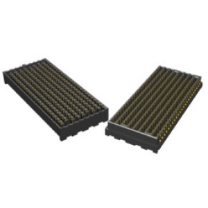
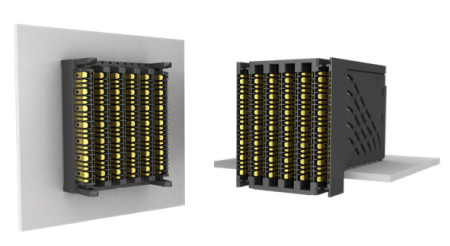
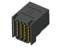
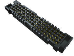
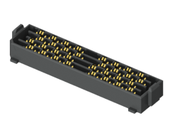
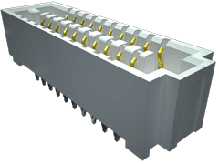
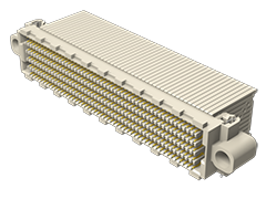
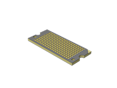
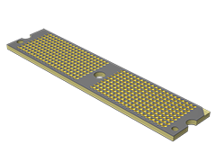
LOW PROFILE ONE-PIECE COMPRESSION ARRAYS
- 1.27 mm and 2 mm standard body heights
- 1.00 mm pitch
- Dual compression or single compression with solder balls
- 100 – 400 total pins
- Ideal for low cost board stacking, module-to-board and LGA interfaces
- Minimizes thermal expansion issues
LOW PROFILE ONE-PIECE COMPRESSION ARRAYS ÜRÜN SERİLERİ
GMI
GMI
AGGREGATE DATA RATE
| Aggregate Data Rate | 448 Gbps | 672 Gbps | 896 Gbps | 896 Gbps | 1344 Gbps | 1792 Gbps | 4032 Gbps* |
| Total No. of Banks | 1 | 1 | 1 | 2 | 2 | 2 | 3* |
| Total No. of Rows | 2 | 3 | 4 | 2 | 3 | 4 | 6* |
| Total No. of Pairs | 8 | 12 | 16 | 16 | 24 | 32 | 72* |
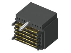
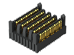
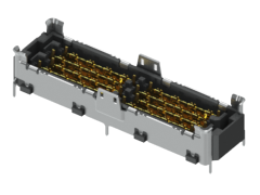
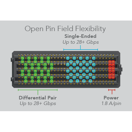
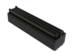
EXTREME PERFORMANCE/DENSITY
- 112 Gbps PAM4 per channel
- 4.0 Tbps aggregate data rate - 9 IEEE 400G channels
- Innovative, fully shielded differential pair design enables:
- Extremely low crosstalk (to 40 GHz)
- Tight impedance control
- Minimal variance in data rate as stack height increases
- 112 differential pairs per square inch
- Utilizes 40% less space than traditional arrays with the same data throughput
- BGA attach to board for greater density and optimized trace breakout region
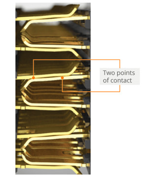
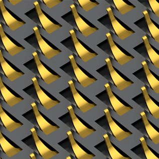
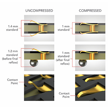
MULTIPLE POINTS OF CONTACT
- Guaranteed two points of contact ensure a more reliable connection
- Stub-free mating
- Signals lost at the first point are caught in the second
- Contributes to the 112 Gbps PAM4 rating
- 92 Ω solution addresses both 85 Ω and 100 Ω applications
The innovative design of NovaRay™ combines extreme density and extreme performance, which is critical as system sizes decrease and speeds increase. The fully shielded differential pair design and two reliable points of contact contribute to the industry leading 4.0 Tbps aggregate data rate.
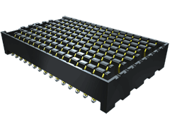
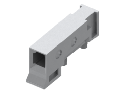
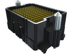
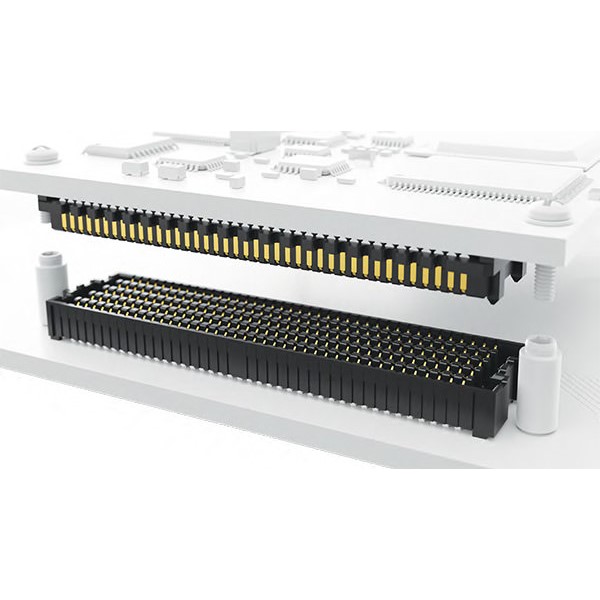
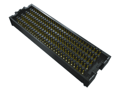
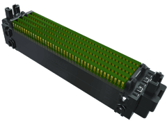
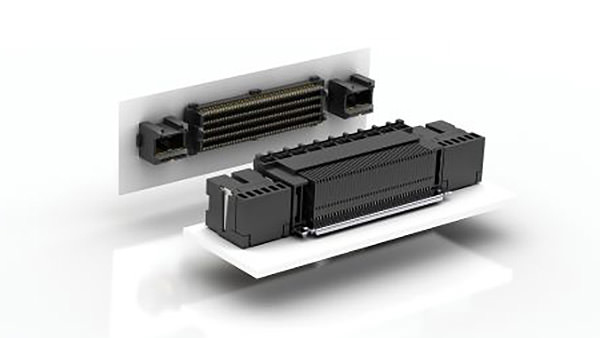
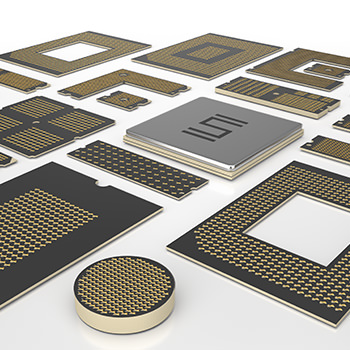
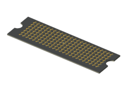
Z-RAY® ULTRA-LOW PROFILE ARRAYS
As a high-speed, high-density connector, Z-Ray® provides the ultimate in design flexibility, from custom heights to full custom geometries. As an interposer, Z-Ray® is a cost-saving removable interface between the IC package and main board. Z-Ray® is ideal for the demands of military/defense, aerospace and R&D applications including radar, radio, navigation and sensors.
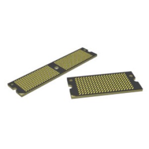
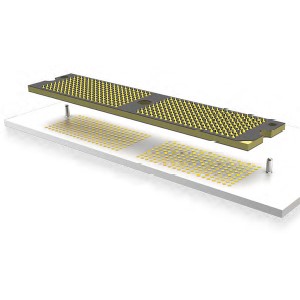
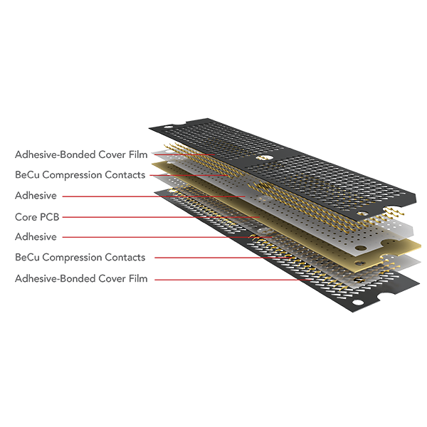
BeCu micro-formed contacts, on 0.80 mm and 1.00 mm pitches, are available in a variety of standard and custom configurations, as dual compression or single compression with solder balls. The contacts are assembled into rugged low-profile FR4 substrate under high pressure and temperature.
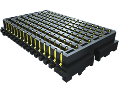
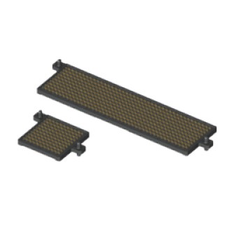
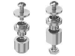
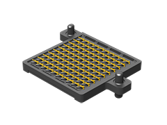
COMPRESSION HARDWARE SYSTEMS
- Engineered to provide precise alignment, compression and retention of dual compression (LGA) or single compression with solder balls (BGA) Z-Ray®Interposers
- Z-Ray® hardware systems are ultra-low profile and designed to reduce risk of damage to the interposer
- ZSO Series provides alignment for single compression solder ball interposers
- ZHSI Series provides alignment and ensures proper contact retention for dual compression interposers
- ZD Series press-in hardware provides proper PCB to interposer alignment for dual compression interposers
CONSTRUCTION
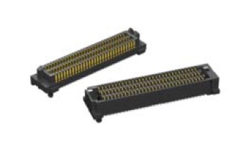
FLEXIBLE DESIGNS
- Configurations for any application, complete with detailed footprints
- Dual compression or single compression with solder balls
- Customer-specific stack heights, pin counts, insulator shapes, and plating thicknesses
- Customizable in the X, Y, and Z axes
- Wide variety of custom geometries
- Quick-turn customization with minimal NRE and tooling charges
- A variety of compression and alignment configurations available
HIGH DENSITY
- Customer-specific pin counts for ultimate high density and speed flexibility
- Choice of 0.80 mm or 1.00 mm pitch grid
- Up to 400 I/Os standard with custom capabilities to 3,000+ I/Os
- Also Available: 1.00 mm pitch system with up to 400 I/Os,1.27 mm and 2 mm standard heights, and up to 56 Gbps performance (GMI Series)
LOW PROFILE
SPECIFICATIONS
- Performance up to 14 Gbps (ZA8, ZA1 Series) and 56 Gbps NRZ (ZA8H Series) with a migration path to 100 Gbps
- Up to 1,000 cycles, with alternate contact design for up to 3,000 cycles also available (tested to 85˚C)
- Low 30 g normal force with .008" contact deflection
- 500 mA per line
- Differential Vias™ PCB routing available
- Also Available: 1.00 mm pitch system with up to 400 I/Os, 1.27 mm and 2 mm standard heights, and up to 56 Gbps performance
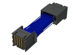
(GMI Series) - Also Available: Ultra-low profile Z-Ray® Cable Assembly designed for high-speed, micro pitch applications (ZRDP Series)